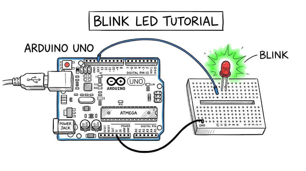
You are sitting in a lab or at your desk, staring at hardware that refuses to work. It is 2 AM. You have checked the code ten times. You swapped the USB cable. You even restarted your laptop. Still nothing works.
This is the reality of hardware prototyping when you start without a clear plan.
I once spent three hours debugging a sensor array for a client in a manufacturing plant in Pune. The issue was not the code. A single jumper wire had a tiny break inside the insulation.
You do not need to go through this.
In 2026, simulation tools help you test faster. You can fail without cost. You can fix issues without damaging components.
This guide shows you how to use Arduino UNO with Tinkercad so you can build systems that actually work.
What is Arduino UNO
The Arduino UNO is the entry point for almost every IoT engineer. You will see it used in labs, startups, and real projects.
It is an open-source microcontroller board based on the Microchip ATmega328P.
You can think of it as a simple computer that runs one program at a time. It does not have an operating system like Windows or Linux.
Once powered on, it runs your instructions from start to end. It stops when power is removed.
The board has 14 digital input/output pins and 6 analog input pins. These allow you to connect sensors, LEDs, and other components.
The Arduino UNO is widely used because it is reliable and easy to work with. It also has a large library of pre-written code.
Whether you are working in a startup in Bangalore or a large company in Dubai, the UNO is often used to build and test ideas before moving to custom hardware.
How it Works
The Arduino UNO works on a simple cycle: fetch, decode, and execute. This is how it processes every instruction.
When you write a program and upload it, the instructions are stored in flash memory on the board.
The ATmega328P chip runs at 16 MHz. This means it can perform around 16 million operations per second.
Many people think the board is “smart.” It is not. It is just fast and follows instructions exactly as written.
When you blink an LED, the board is simply switching a pin between 0V and 5V. That is all it does.
On the software side, you use the Arduino IDE to write your code. The language is based on C++.
The compiler converts your code into machine-readable hex format.
The bootloader on the chip ensures the program starts running as soon as the board gets power.
There is a direct link between your code and physical output. What you write controls real electrical signals.
Technical Flow and Architecture
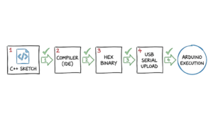
The technical flow of an Arduino project follows a specific chain: Code → Compilation → Upload → Execution. When you click “Start Simulation,” the Tinkercad engine creates a virtual instance of the ATmega328P. It maps your virtual wires to a simulated electrical grid. Every time your code calls a function like digitalWrite(), the simulator calculates the voltage drop across your virtual components.
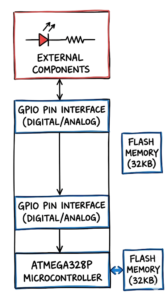
The architecture relies on the Harvard architecture, where program memory and data memory are separate. You have 32 KB of flash memory for your code. That sounds tiny compared to your phone, but for a blink led project, it is more than enough. The data flows through the General Purpose Input/Output pins. These pins are the physical interface. If you set a pin to HIGH, the board tries to push 5V out. If you set it to LOW, it connects that pin to ground.
Key Components
To build your first simulation, you need to understand the tools in your virtual kit. Tinkercad provides a tray of components that behave exactly like their physical counterparts.
- Arduino UNO R3: This is the brain that stores your instructions and provides the power logic for the circuit.
- LED: This is a semiconductor that emits light when current flows through it in the correct direction.
- Resistor 220 Ohm: This component limits the flow of current to prevent the LED from receiving too much power and burning out.
- Breadboard: A plastic grid that allows you to connect components together without using a soldering iron or glue.
- Jumper Wires: These are the virtual cables that act as the circulatory system for your electricity.
Practical Implementation
Follow these steps to build your first blink led project. Do not skip the resistor. Many juniors think they can bypass it because it is “just a simulation,” but building bad habits now will cost you real money when you move to physical hardware.
- Open Tinkercad and create a new “Circuit” design from your dashboard.
- Drag the Arduino UNO R3 from the component list and place it in the center of your workspace.
- Locate the “Small Breadboard” and place it next to the board to give yourself room for wiring.
- Pick a red LED and snap it into the breadboard, making sure the two legs are in different numbered rows.
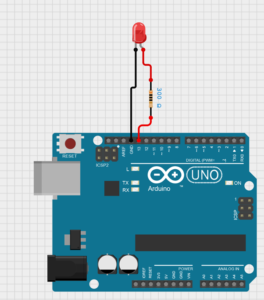
- Connect a 220 Ohm resistor from the row containing the shorter leg (the cathode) to the long blue ground rail on the side of the breadboard.
- Run a black jumper wire from the “GND” pin on the Arduino to that same blue ground rail on the breadboard.
- Run a red jumper wire from Digital Pin 13 on the board to the row containing the longer leg (the anode) of your LED.
- Click the “Code” button, switch the editor type to “Text,” and paste the standard blink program into the window.
Basic Arduino Program for LED Blink
Copy this exact code into your editor. This is the “Hello World” of the IOT industry.
C++
————————————————————————————————————
void setup() {
// initialize digital pin LED_BUILTIN as an output.
pinMode(LED_BUILTIN, OUTPUT);
}
// the loop function runs over and over again forever
void loop() {
digitalWrite(LED_BUILTIN, HIGH); // change state of the LED by setting the pin to the HIGH voltage level
delay(1000); // wait for a second
digitalWrite(LED_BUILTIN, LOW); // change state of the LED by setting the pin to the LOW voltage level
delay(1000); // wait for a second
}
________________________________________________________________________________________________________
Now here’s where it gets interesting: the LED_BUILTIN variable is actually just a shortcut for Pin 13. Most Arduino boards have a tiny LED soldered directly to the board on that pin. By wiring your external LED to Pin 13, you are making both the on-board light and your external light blink at the same time.
Circuit Diagram
Advantages and Limitations
Simulation is a powerful tool, but it is not perfect. In real environments, it doesn’t work this cleanly. A simulator assumes your wires have zero resistance and your power supply is perfectly stable. In the real world, you deal with electromagnetic interference, loose connections, and heat.
The advantage of using Tinkercad is that you can visualize the current. If you remove the resistor, the simulator will show an explosion icon over the LED. This teaches you the importance of current limiting without costing you five dollars for a new LED. However, a limitation is that the timing in a browser-based simulator might lag if your internet connection is slow. Do not rely on a simulator for high-precision timing applications like high-speed motor control or complex signal processing.
Common Mistakes
Most beginners fail because they treat electronics like software. They think if the logic is right, the project is right. That is false.
- Backward LEDs: This is where most people get confused. An LED is a diode. It only works in one direction. If you put the long leg in the ground side, nothing happens.
- Semicolons: If you come from a Python background, you will hate this. Every line in Arduino needs a semicolon.
- Floating Pins: If you set a pin as an input but don’t connect it to a defined voltage, it will give you “ghost” data. Always use a pull-up or pull-down resistor for inputs.
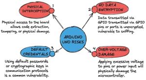
- Powering too much: Never try to run a large motor directly from an Arduino pin. You will pull too much current and kill the ATmega328P. Use a transistor or a relay.
Best Practices
If you want to move from a junior to a senior, you need to write clean code and build clean circuits. Use red wires for positive power and black wires for ground. It sounds simple, but when you have a circuit with 50 wires, color-coding is the only thing that will save your sanity.
Comment your code. Even in a simple blink led script, explain why you chose a specific delay. If you are working on an enterprise project, like a Saudi petrochemical plant monitoring system, your code will be reviewed by other engineers. If they cannot understand your logic in thirty seconds, you have failed as a developer.
Troubleshooting Scenario
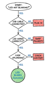
Scenario: You have clicked “Start Simulation.” The code says it is running, but the LED is dark.
The wrong assumption: Most juniors assume the code is broken and start rewriting the loop() function. They think they need a different library or a more complex algorithm.
The actual fix: 90 percent of the time, the hardware wiring is the issue. Look at the LED. Is it connected to Pin 13 or Pin 12? If your code says 13 and your wire is in 12, it stays dark. Check the resistor value. If you accidentally set it to 220 kilo-ohms instead of 220 ohms, the resistance is so high that not enough current can pass to light the LED. Check the ground. If the black wire isn’t connected to the “GND” pin, the circuit isn’t complete. Electricity is like water: if there is no path back to the source, nothing flows.
Interview Questions
Q: What is the difference between delay() and millis()?
A: delay() is a blocking function that stops all execution. millis() returns the time since the board started, allowing you to create non-blocking timers for multi-tasking.
Q: Can you power an Arduino UNO with a 9V battery?
A: Yes, through the DC barrel jack. The on-board voltage regulator will step it down to the 5V required by the microcontroller.
Q: What happens if you connect a 5V pin directly to GND?
A: You create a short circuit. On a computer’s USB port, this might trigger a port reset. On a raw battery, it could cause the regulator to overheat and fail.
Q: Why do we use pinMode() in setup()?
A: You must tell the microcontroller whether a pin should act as a “tap” (OUTPUT) providing electricity or a “sensor” (INPUT) listening for it.
Q: What is the purpose of the 16MHz crystal on the board?
A: It acts as the heartbeat of the CPU, providing a steady pulse so the processor can execute instructions at a predictable speed.
Future Trends 2026 and Beyond
As we move deeper into 2026, the Arduino UNO is becoming a gateway to Edge AI. We are seeing more juniors using “TinyML” to run small machine learning models directly on microcontrollers. This means your blink led project could soon turn into a “blink only when I see a specific face” project.
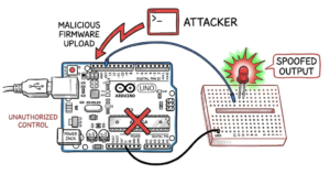
In regions like the GCC and India, there is a massive shift toward the Matter protocol for smart homes. Future Arduino boards are integrating this standard natively. Additionally, with the rise of quantum computing threats, we are seeing the early stages of Post-Quantum Cryptography (PQC) being adapted for 8-bit and 32-bit sensors. You will soon need to understand how to secure even the simplest temperature sensor against advanced decryption methods.
FAQ
Can I run the same code on an Arduino Nano?
Yes. The Nano uses the same ATmega328P chip as the UNO. The only difference is the physical size and the USB connector type. Your code and wiring logic remain the same.
How many LEDs can one Arduino UNO control?
Technically, you can control one LED per digital pin, which is 14. However, you must be careful not to exceed the total current limit of the chip, which is usually around 200mA total.
Why is my LED dim in the simulation?
Check your resistor value. If the resistance is too high, the current is restricted. For a standard red LED on a 5V circuit, a resistor between 220 and 330 ohms is ideal.
Do I need to install drivers for Tinkercad?
No. Tinkercad runs entirely in your web browser. This makes it ideal for engineers working on locked-down corporate laptops or in university labs with restricted access.
What is the difference between a microcontroller and a microprocessor?
A microcontroller like the one on the Arduino has a CPU, RAM, and storage all on one chip. A microprocessor, like the one in your laptop, requires external components to function.
Can I use Tinkercad on a tablet?
Yes, but it is difficult. The circuit editor is designed for a mouse and keyboard. For serious engineering work, use a desktop or a laptop.
How do I save my work in Tinkercad?
Tinkercad saves your progress automatically to the cloud. You can close the tab at any time and your circuit will be waiting for you in your dashboard.
Conclusion
The transition from code to physical action is what defines an IOT engineer. By mastering the Arduino UNO in a simulated environment, you have built the logical framework required for enterprise-grade automation. Whether you are working for a telecom giant in Riyadh or a fintech startup in Singapore, these fundamentals do not change. Take the code you used today and try to change the blink frequency. Modify the delay to 500ms and see how the rhythm changes. Once you can control a single light, you can control a city. Stop reading and go build your first circuit.
Refernce: Arduino Documentation
If you want to move beyond basic projects and build secure IoT systems, read this complete guide:
IoT security risks and best practices